Product Description
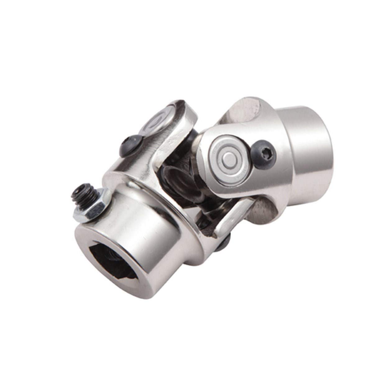
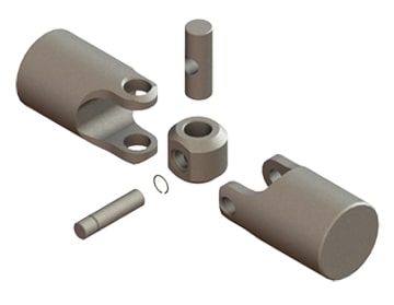
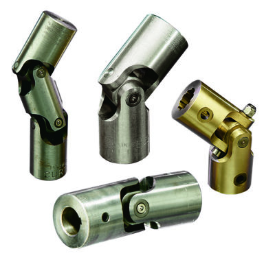
Universal joint description
1>it is FOB HangZhou price . (also can send free to HangZhou HangZhou /ning bo ZheJiang and so on. warehouse .)
2>the material is 20cr good material , must not any complain from your customers. (also have 20Mn . 20cr Mn Ti )
3>our delivery time is 40days (with 20Gp container ) . very in time .
4> Can develop according to customer’s drawings or samples
5> OEM is available
6> Full range for the universal joint
7> Good quality and resonable price
Packaging & Delivery
the packing . Standard netural packing with carton.
Delivery detail: 30-45 working days,depend on the actual produce condition
FAQ
Q1: What is the location of your company?
A1: Our company is located in the CHINAMFG Zhou(Jin jiang) City ,Fu jian province,China.Welcome to visit our factory at anytime!
Q2: How does your factory do regarding quality control?
A2: Our standard QC system to control quality(TS16949 2016).
Q3: What is your delivery time?
A3: Usually within 30-40 days after the receipt of payment.Delivery time must depend on the actual produce condition.
Q4: What are your strengths?
A4: 1.We are the manufacturer,having competitive advantage in price.
2.A large part of money is put into advancing CNC equipments and product
R&D department annual,the performance of universal joint can be guaranteed.
3.About quality issues or follow-up after-sales service,we report directly to the boss.
Specification
There is no uniform standard for the specifications of cross assemblies. Please contact us directly for confirmation.
/* March 10, 2571 17:59:20 */!function(){function s(e,r){var a,o={};try{e&&e.split(“,”).forEach(function(e,t){e&&(a=e.match(/(.*?):(.*)$/))&&1
| Condition: | New |
|---|---|
| Color: | Natural Color |
| Certification: | CE, ISO |
| Structure: | Single |
| Material: | Stainless Steel |
| Type: | 20mn 20cr 20crmnti |
| Samples: |
US$ 49.7/Piece
1 Piece(Min.Order) | |
|---|
| Customization: |
Available
| Customized Request |
|---|

How do you ensure proper alignment when connecting a universal joint?
Ensuring proper alignment when connecting a universal joint is essential for its optimal performance and longevity. Here’s a detailed explanation:
Proper alignment of a universal joint involves aligning the input and output shafts to minimize angular misalignment and maintain a smooth and efficient power transfer. Here are the steps to ensure proper alignment:
- Measure shaft angles: Begin by measuring the angles of the input and output shafts that the universal joint will connect. This can be done using a protractor or an angle measuring tool. The angles should be measured in relation to a common reference plane, such as the horizontal or vertical.
- Calculate the operating angle: The operating angle of the universal joint is the difference between the angles of the input and output shafts. This angle determines the amount of angular misalignment that the universal joint needs to accommodate. It is crucial to calculate the operating angle accurately to ensure the proper selection of a universal joint suitable for the application.
- Select the appropriate universal joint: Based on the calculated operating angle, choose a universal joint that is designed to handle the specific misalignment requirements. Universal joints come in various sizes and designs to accommodate different operating angles and torque loads. Refer to the manufacturer’s specifications and guidelines to select the appropriate universal joint for the application.
- Achieve parallel alignment: To ensure proper alignment, it is important to align the input and output shafts so that they are parallel to each other when viewed from the common reference plane. This can be achieved by adjusting the mounting positions of the shafts or using alignment tools such as straightedges or laser alignment systems. The goal is to minimize any offset or skew between the shafts.
- Check centerline alignment: Once the shafts are parallel, it is necessary to check the centerline alignment. This involves verifying that the centerline of the input shaft and the centerline of the output shaft are in line with each other. Misalignment in the centerline can result in additional stress on the universal joint and lead to premature wear or failure. Use measurement tools or visual inspection to ensure the centerline alignment is maintained.
- Securely fasten the universal joint: After achieving proper alignment, securely fasten the universal joint to the input and output shafts according to the manufacturer’s recommendations. Follow the specified torque values for the fasteners to ensure proper clamping force without over-tightening. This will help maintain the alignment during operation.
- Perform regular maintenance: To ensure continued proper alignment, it is important to perform regular maintenance, including periodic inspections and lubrication of the universal joint. Regular maintenance can help detect any misalignment or wear issues early on and prevent further damage or failure.
By following these steps and paying attention to proper alignment, the universal joint can operate smoothly and effectively, minimizing stress, wear, and the risk of premature failure.
In summary, ensuring proper alignment when connecting a universal joint involves measuring shaft angles, calculating the operating angle, selecting the appropriate universal joint, achieving parallel alignment, checking centerline alignment, securely fastening the joint, and performing regular maintenance.

How do you calculate the operating angles of a universal joint?
Calculating the operating angles of a universal joint involves measuring the angular displacement between the input and output shafts. Here’s a detailed explanation:
To calculate the operating angles of a universal joint, you need to measure the angles at which the input and output shafts are misaligned. The operating angles are typically expressed as the angles between the axes of the two shafts.
Here’s a step-by-step process for calculating the operating angles:
- Identify the input shaft and the output shaft of the universal joint.
- Measure and record the angle of the input shaft relative to a reference plane or axis. This can be done using a protractor, angle finder, or other measuring tools. The reference plane is typically a fixed surface or a known axis.
- Measure and record the angle of the output shaft relative to the same reference plane or axis.
- Calculate the operating angles by finding the difference between the input and output shaft angles. Depending on the arrangement of the universal joint, there may be two operating angles: one for the joint at the input side and another for the joint at the output side.
It’s important to note that the specific method of measuring and calculating the operating angles may vary depending on the design and configuration of the universal joint. Some universal joints have built-in methods for measuring the operating angles, such as markings or indicators on the joint itself.
Additionally, it’s crucial to consider the range of acceptable operating angles specified by the manufacturer. Operating a universal joint beyond its recommended angles can lead to increased wear, reduced lifespan, and potential failure.
In summary, calculating the operating angles of a universal joint involves measuring the angular displacement between the input and output shafts. By measuring the angles and finding the difference between them, you can determine the operating angles of the universal joint.

How does a universal joint accommodate misalignment between shafts?
A universal joint, also known as a U-joint, is designed to accommodate misalignment between shafts and allow for the transmission of rotational motion. Let’s explore how a universal joint achieves this:
A universal joint consists of a cross-shaped or H-shaped yoke with bearings at the ends of each arm. The yoke connects the input and output shafts, which are not in line with each other. The design of the universal joint enables it to flex and articulate, allowing for the accommodation of misalignment and changes in angles between the shafts.
When misalignment occurs between the input and output shafts, the universal joint allows for angular displacement. As the input shaft rotates, it causes the yoke to rotate along with it. Due to the perpendicular arrangement of the yoke arms, the output shaft connected to the other arm of the yoke experiences rotary motion at an angle to the input shaft.
The flexibility and articulation of the universal joint come from the bearings at the ends of the yoke arms. These bearings allow for smooth rotation and minimize friction between the yoke and the shafts. They are often enclosed within a housing or cross-shaped cap to provide protection and retain lubrication.
As the input shaft rotates and the yoke moves, the bearings within the universal joint allow for the necessary movement and adjustment. They enable the yoke to accommodate misalignment and changes in angles between the input and output shafts. The bearings allow the yoke to rotate freely and continuously, ensuring that torque can be transmitted smoothly between the shafts despite any misalignment.
By allowing angular displacement and articulation, the universal joint compensates for misalignment and ensures that the rotation of the input shaft is effectively transmitted to the output shaft. This flexibility is particularly important in applications where shafts are not perfectly aligned, such as in automotive drivelines or industrial machinery.
However, it’s important to note that universal joints do have limitations. They introduce a small amount of backlash or play, which can affect precision and accuracy in some applications. Additionally, at extreme angles, the operating angles of the universal joint may become limited, potentially causing increased wear and reducing its lifespan.
In summary, a universal joint accommodates misalignment between shafts by allowing angular displacement and articulation. The bearings within the universal joint enable the yoke to move and adjust, ensuring smooth and continuous rotation between the input and output shafts while compensating for their misalignment.


editor by CX 2024-01-29